Automobile hacking is one of the leading-edge areas of our hacking discipline. As our automobiles have become smarter and smarter, they include more and more electronics, making them more and more vulnerable. As we are literally and figuratively turning the corner into the era of the driver-less or autonomous car, hacking automobiles will become even more important and dangerous.
In this series, we will examine the basics of automobile hacking and advance to more complex hacking strategies. For an example of rather simple automobile hacking, check out my article on hacking the Mitsubishi Outlander.
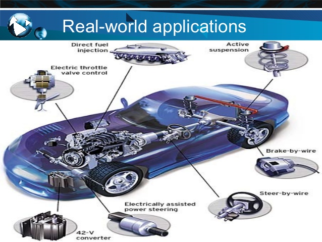
Before we can delve into automobile hacking, we need to first understand the basics. Kind of like understanding TCP/IP before network hacking or modbus before SCADA hacking. Automobile electronics use several different protocols to communicate between the multiple micro-controllers, sensors, gauges, actuators, etc. The most widely used of these protocols is the Controller Area Network or CAN.
The CAN Protocol
CAN was first develop by Robert Bosch GmbH, the German industrial giant known for their automotive electronics. It was first released at the Society of Automotive Engineers (SAE) meeting in 1986. The CAN protocol has been standardized as ISO 11898-1 and ISO 11898-2. It was designed for robust communication within the vehicle between micro-controllers and devices without the need of a host computer.
CAN operates as broadcast type of network, similar to a broadcast packet in Ethernet or using a hub in the old days of networking (1980-90’s). Every node on the network can “see” every transmission. Unlike Ethernet or TCP/IP (but similar to modbus in SCADA systems) you can not send a message to a single node, but the CAN does provide for local filtering so that each node only acts upon messages pertinent to its operation. You can think of this as “content messaging”, where the contents determine the target node.
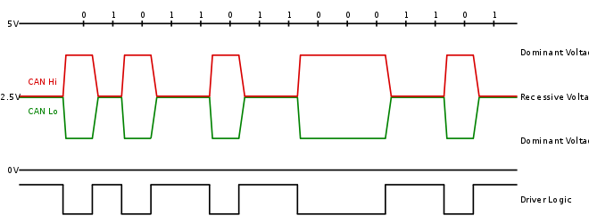
CAN runs over two wires, CAN high and CAN low. Due to the “noise” inherent in automobile systems, CAN uses differential signaling. This is where the protocol raises and lowers the voltage on the two wires to communicate. In both high speed and low speed CAN, signaling drives the high wire towards 5v and the low wire towards 0v when transmitting a zero (0) but doesn’t drive either wire when sending a one (1).
CAN Message Types
CAN uses four (4) different types of messages;
1. Data Frame
2. Remote Frame
3. Error Frame
4. Overload Frame
Data Frame
This is the only frame actually used for data transmission. In most cases, the data source node sends the data frame.
It has two types, standard and extended. The standard has 11 identifier bits and the extended has 29 bits. The CAN standard requires that the base data frame MUST be accepted and the extended frame MUST be TOLERATED, in other words it will not break the protocol or transmission.
Remote Frame
The remote frame is used when the data destination node requests the data from the source.
Error Frame
The error frame has two different fields, the first is given by the ERROR FLAGS and contributed by the different stations and the second is the ERROR DELIMITER, simply indicating the end of the error message
Overload Frame
The overload frame has two fields. These are the Overload Flag and the Overload Delimiter. The overload frame is triggered when either by the internal conditions of a receiver or the detection of dominant bit (0) during transmission.
The On Board Diagnostics (OBD)-II Connector
Most vehicles now come with an ODB-II connector. If you have taken your car to a shop for repair, it is this connector under the dashboard where the mechanic connects their computer to get a read on the on-board computers.
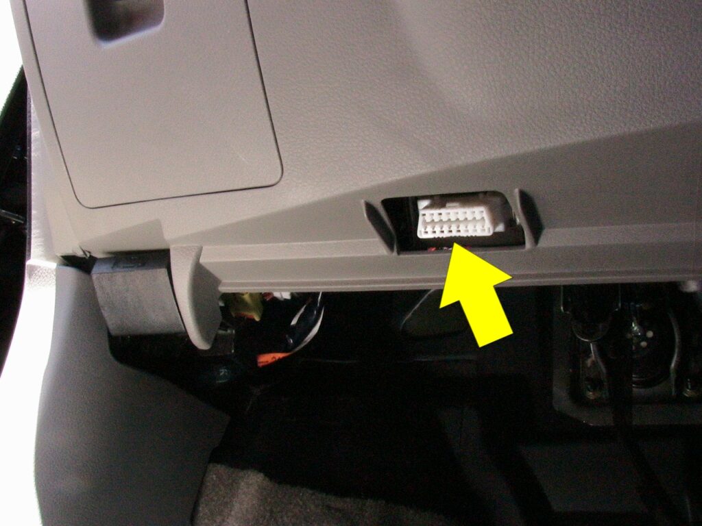
The OBD-II has 16 pins and looks like the diagram below.
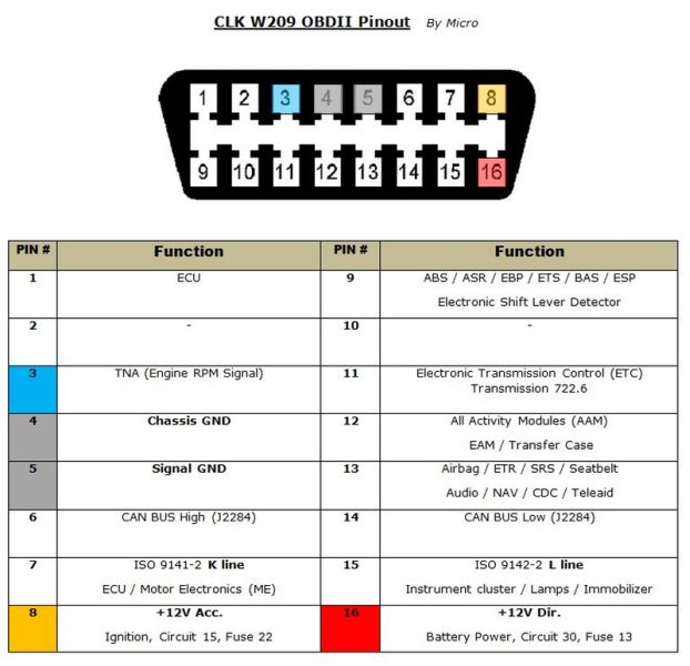
As a hacker/attacker, we also can connect to this OBD-II connector and send messages on the CAN network to various devices.
CAN Bus Packet Layout
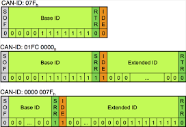
There are two types of CAN packets, standard and extended. The extended packets share the same same elements as the standard packet, but the extended packets have additional space to include ID’s.
Standard Packets
Every CAN packet has four critical sections. These are;
Arbitration ID
The arbitration ID is the ID of the device sending the packet.
Identifier Extension
This bit is always 0 for standard CAN
Data Length Code (DLC)
This indicates the size of the data, from 0 to 8 bytes
Data
This is the data in the message. As mentioned above, it can be up to 8 bytes.
As mentioned above, all CAN packets are broadcast so ever device or controller can see every packet. There no way for any device to know which controller sent the packet (no return address), so spoofing messages on a CAN network is trivial. This is one of the key weaknesses of CAN.
Extended CAN Packets
Extended CAN packets are the same as standard CAN packets, but they are chained together to create longer ID’s. Extended CAN is backwardly compatible with standard CAN. This means that if a sensor was not designed to accept extended CAN packets, this system won’t break.
Security
Due to CAN being a low-level protocol, it does not have any security features built in. It has NO encryption or authentication, by default. This can lead to man-in-the middle attacks (no encryption) and spoofing attacks (no authentication). Manufacturers in some cases have implemented authentication mechanisms on mission critical systems such as modifying software and controlling brakes, but they have not been implemented by all manufacturers. Even in the cases where passwords have been implemented, they are relatively easy to crack.
As we progress through this series on automobile hacking, we will expand upon your understanding of CAN and the other automobile communication protocols. It might be useful to bookmark this page for future reference.
You can proceed to Part 2 of this series here.
Look for my upcoming Automobile Hacking LIVE Online course!
